 I understand that most people will not find this post too exciting … but I am excited!
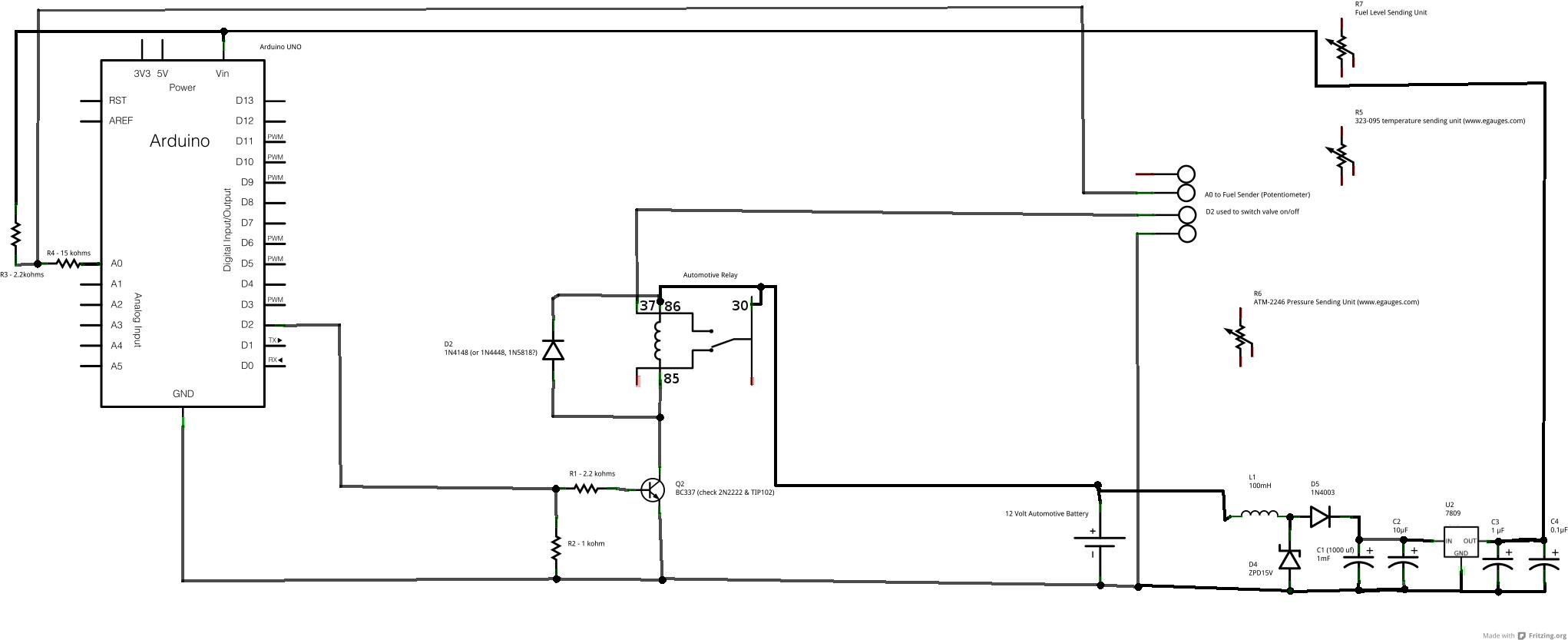
I have been working on an ECU (electronic control unit or more simply computer) for the WVO system. My current operating schematic (ECU_schem) is as shown in this post.
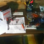
 I finally got some of the parts laid out on a breadboard and tested it this evening … and it worked! The Arduino controller and circuit:
- controlled an automotive relay (turned it off and on),
- monitored the variable resistance from the fuel sending unit (in other words read the level of oil in the WVO tank),
- and operated off of a 12 volt battery.
Item 3 is actually of the most concern to me right now because being hooked up to a car’s electrical system is actually a pretty harsh environment for the Arduino. The alternator generates a lot of spikes and noise that can damage the circuit if not accounted for. I will be curious to see how this part of the circuit works when connected to the running vehicle. The parts in the circuit dealing with regulating the voltage from the car include:
- L1 – an inductive coil that is supposed to reduce electrical noise generated by the alternator (the value for this may be off … I was aiming for 40 microH and wound up with a 100 microH part),
- D4 – A zener diode that should limit voltage spikes to 15V (apparently the alternator can spike up to 20 volts … which would definitely be bad for the Arduino),
- D5 – A diode to prevent an incorrectly connected battery from damaging the Arduino,
- U2 – a 9 volt voltage regulator … this is not necessary for the Arduino as it should be able to regulate the voltage provided after D5 … I wanted a constant 9 volts for any analog inputs I add … the analog inputs use a voltage divider to read a value and if this voltage is variable (like what is coming off the battery) the readings will fluctuate,
- C1-C4 – Capacitors for the voltage regulator U2.
Item 1 was relatively straight forward. I am using a digital output from the Arduino to turn on a transistor and switch an automotive relay. An automotive relay is probably massive overkill for what I am doing … but it is definitely safe. You could also apparently do the same thing with a MOSFET transistor and skip the relay … I was unsure of this so stuck with the automotive relay. I will need at least two of these circuits to control the two electric WVO valves. Some notes on the parts used here:
- R2 is a pull down resistor that guarantees that if the controller is not working the relay will not click on,
- D2 is a reverse biased diode that protects against a current spike when the relay is turned off,
- Q2 is an NPN transistor used with an Arduino digital output pin to switch the relay,
- R1 limits the current drawn from the Arduino pin,
- The pin labelled 37 on the automotive relay should read 87.
Item 2, the voltage divider, has been tested and works. I will probably use a smaller resistor here so that I get a larger range of readings on the Arduino anolog input. I will need at least 3 of these voltage dividers (on 3 separate input pins to monitor temperature, pressure and oil level).
- R4 is a series resistor again used to protect the Arduino,
- R3 is the fixed resistor for the voltage divider and I will probably use a smaller resistor here (300-500 ohms?),
- R5,R6,R7 are the variable resistors for the voltage dividers for the analog readings. (the sending units)
Not shown in the circuit is the LCD display that I connected to the breadboard. The LCD that I used is pretty generic and I followed the tutorial at http://arduino.cc/en/Tutorial/LiquidCrystal to get it working. Ultimately, I want to get the Arduino talking to my Android based phone and I think I will use bluetooth for that initially. I may leave the LCD in so that there is always some interface to the WVO controller if the phone is not in the car … that also means that I should have a few buttons connected to the controller.
The next step is to solder a board and test it in the car … I am getting closer!
The testing code I used on the Arduino is:
// include library code
#include <LiquidCrystal.h>

// initialize the library with the numbers of the interface pins
LiquidCrystal lcd(12, 11, 5, 4, 3, 2);

  /*
   Proc: lcdInit - Initialize the LCD display
   Returns: initialized LCD object

   Initialize a 16x2 LCD display.  The LiquidCrystal
   library works with all LCD displays that are compatible with the
   Hitachi HD44780 driver. There are many of them out there, and you
   can usually tell them by the 16-pin interface.

  The circuit:
 * LCD RS pin to digital pin 12
 * LCD Enable pin to digital pin 11
 * LCD D4 pin to digital pin 5
 * LCD D5 pin to digital pin 4
 * LCD D6 pin to digital pin 3
 * LCD D7 pin to digital pin 2
 * LCD R/W pin to ground
 * 10K resistor:
 * ends to +5V and ground
 * wiper to LCD VO pin (pin 3)

 */

void lcdInit () {
  // set up the LCD's number of columns and rows:
  lcd.begin(16, 2);

  // Print a message to the LCD.
  lcd.print("Initializing");

  return;
}

void lcdWriteMessage (String str, int iLine)
{
  // set the cursor to column 0, line 1
  // (note: line 1 is the second row, since counting begins with 0):
  lcd.setCursor(0, iLine);
  // print the number of seconds since reset:
  lcd.print(str);
}

/*
 * Notes: 2200 ohm pullup resistor (13 full ; 102 empty)
 *        220 ohm pullup resistor (183 full ; 544 empty)
 *        10 K pullup resistor (1 full ; 22 empty)
 */

int iFuelLevelInput = A0; // a0
int iRelayOutput = 8;     // D8

void setup(void) {
  // Setup the pins
  pinMode(iRelayOutput, OUTPUT);
  pinMode(iFuelLevelInput, INPUT);

  // We'll send debugging information via the Serial monitor
  Serial.begin(9600);

  // Set the levels of the output pins
  digitalWrite(iRelayOutput, LOW);

  lcdInit();
}

void loop(void) {
  int iFuelLevel;

  iFuelLevel = analogRead(iFuelLevelInput);

 lcdWriteMessage("Fuel Lvl: ", 0);
 lcd.print(iFuelLevel);

  lcdWriteMessage("ON ", 1);
 digitalWrite (iRelayOutput, HIGH);
 delay(1000);
 lcdWriteMessage("OFF", 1);
 digitalWrite (iRelayOutput, LOW);
 delay (1000);
}
Why not use solar to power the circuit? Maybe I don’t understand everything. I purchased a arduino to to use in my chicken coup but had zo many other things I need to do first. What got me to your site was the rocket stove, been researching to put in my basement. Since I can’t afford thr propane. Slowly getting insulated to my standards but having allot of health issues. Thanks for the information, Paul.
Hi Paul,
That specific circuit is for a waste vegetable oil controller in the van … it makes more sense to power it off the vehicle battery in this case.